 Go to JKU Homepage

Maria Thumfart

Supervision: Univ.-Prof. Dipl.-Ing. Dr. Bernhard Zagar
With clock frequencies ever increasing in digital circuits inductive coupling problems are becoming more and more important. The following two model problems are designed to show the effects of inductiv coupling and sensitivity of circuits to electrostatic discharge:
Lab exercise 1: magnetic field coupling
The problem consists of a 2m coaxial cable, a low resistance connection between the two ends of the outer conductor and a split of the outer conductor and inner conductor in order to be able to measure the currents in the outer conductor.
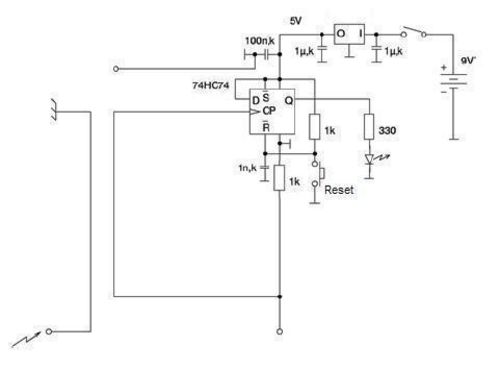 Figure 1: Schematic of problem 2
The 3,3Ohm resistor (in the outer conductor) is there to reduce the influence of the junctions' resistance on the result. The Students now expect almost the whole current to take the low resistance connection. What is true for low frequencies. The higher the frequency the more current is taking the way through the outer connector of the coaxial cable. That should show to the students that it is important to consider the inductance of a current path on a print and not only the resistance.
Lab exercise 2: electrostatic discharge
Because the dimensions used to demonstrate magnetic field coupling in lab exercise 1 are big compared to a printed circuit boards' size the students might think the problem doesn't need to be considered on a small printed circuit board.
In this problem a D-flip-flop is used as an indicator to detect pulses coupled through transient magnetic field into a clock wire on a wire whose layout is is badly designed. In this problem it is easily shown that the placement of wires and electromagnetic shielding on a print is essential for the immunity to outer and inner interferences.
April 20, 2007