Dipl.-Ing. Dr. Klaus Oppermann

Supervisory committee: | Univ.-Prof. Dipl.-Ing. Dr. Bernhard Zagar |
Final exam: | September 19, 2011 |
This work was developed in the course of an FFG, opens an external URL in a new window-project with the title “Robust highly dynamic force sensor for agricultural engineering” under the project number 814325 together with the Alois Pöttinger company, opens an external URL in a new window. The magneto-elastic effect was first identified by E. VILLARI in 1865 by that reason the effect is also known by the name Villari effect. The first commercially available sensor was introduced by the company ABB, opens an external URL in a new window in 1954 and was called Pressductor.
It featured a very high overload factor, high signal levels and is able to operate at very rough environmental conditions. But there are also some drawbacks of these kind of sensors: ageing effects, temperature depending sensitivity, zero drift and hysteresis error.
So a prototype consisting of the sensor and its electronic was constructed and built. By the reason that ABB uses steel as sensor material there is the question if this sensing effect in combinationof a novel material and modern digital signal processing can reach a wider application area. So a magneto-elastic force sensor based on a novel sensing material was developed, which is a rare earth alloy of terbium, dysprosium and iron. This alloy is called Terfenol-D and was chosen as sensor material, because of its very high magneto-mechanical coupling factor as compared to the typically used material steel. This new sensor should retain all the benefit, the very high overload factor and the robustness, of these kind of sensors and also minimize their disadvantages with modern digital signal processing.
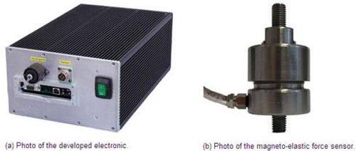
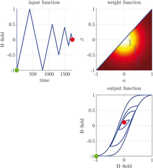
During the electrical and mechanical characterization of the sensor system (see figure 1) a rather large hysteresis span of the sensor signal was noticed. Hence the main chapter of the work, modelling and compensation of a hysteresis, is following. In this chapter many hysteresis models like the Preisach, the Jiles-Atherton and the Coleman-Hodgdon are taken under investigation to describe the hysteresis of the developed sensor. After an evaluation process the Preisach model (siehe figure 2) is chosen. Even though this model has the drawback that the calculation is rather time consuming especially for the high precision aimed for, this model was adapted and further developed to achieve the aim of a real time hysteresis compensation.
 (a) Photo of the developed electronic. (b) Photo of the magneto-elastic force sensor.
Figure 1: Picture of the two components of the magneto-elastic force sensor system.
 Figure 2: Schematic illustration of the Preisach hysteresis model with a Gaussian weight function µαβ.The upper left figure shows the input function of the model and the upper right figure shows the Preisach operator γα,β with the weight function superposed in the background. The lower right figure shows the output hysteresis function of the model, in which the green point describes the beginning of the hysteresis and the red point describes the ending.
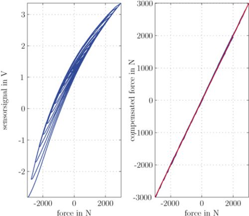
 Figure 3: Illustration of a measurement cycle of the magneto-elastic force sensor with real time hysteresis compensation. In the left figure the measured raw sensor signal is shown and in the right figure the compensated signal of the sensor is shown. The red line in the right figure represents the correct result.
The rather complex identification process is explained in detail and a rather simple and smart method for identification of the further developed model is shown.
Then the hysteresis compensation was directly implemented into the DSP, therefore the extended Preisach model had to be inverted to be able to compensate the hysteresis of the sensor in real time.
Towards the end the complete developed system is verified with a more complex test cycle including real time hysteresis compensation to show the capability of the system. The results of the real time hysteresis compensation are shown in figure 3. The left figure shows the raw sensor signal and the right figure shows the compensated signal.
The circulation of the project work is restricted from September 6, 2011, for a period of 5 years.
 Go to JKU Homepage


