 Go to JKU Homepage

Dipl.-Ing. Dr. Stefan J. Rupitsch

Supervisory committee: | |
|---|---|
Final exam: | |
Univ.-Prof. Dipl.-Ing. Dr. Bernhard Zagar | August 21, 2008 |
Supervisory committee: | Univ.-Prof. Dipl.-Ing. Dr. Bernhard Zagar |
Final exam: | August 21, 2008 |
The objective of this thesis is the development of a high resolution ultrasound microscope for non-destructive material testing. The realized microscope (see Figure 1) operates using a focused ultrasound transducer with a spherically curved active surface. By means of the transducer pressure waves are emitted as well as received. Synthetic aperture focusing (SAFT) is applied in order to achieve the optimal spatial resolution of the imaging system. This technique combines a sequence of transducer output signals at different transducer positions to improve spatial resolution.
Although synthetic aperture focusing essentially increases the spatial resolution, an additional improvement of the resolution is aspired in this thesis. On this account the locally resolved characteristic of the transducer surface for both transmission and reception is considered (see Figure 2). In order to determine the transducers spatial-temporal characteristic a novel method is presented in this thesis. As part of this method an ill-posed inverses problem is solved. The developed ultrasound microscope can be used to acquire B-mode images ("brightness") as well as C-mode images ("complex") of the object under test. For instance the microscope is able to precisely locate regions where delaminations of layered material occur (see Figure 3). Moreover the bonding areas of semiconductors and their connecting wires can be investigated.
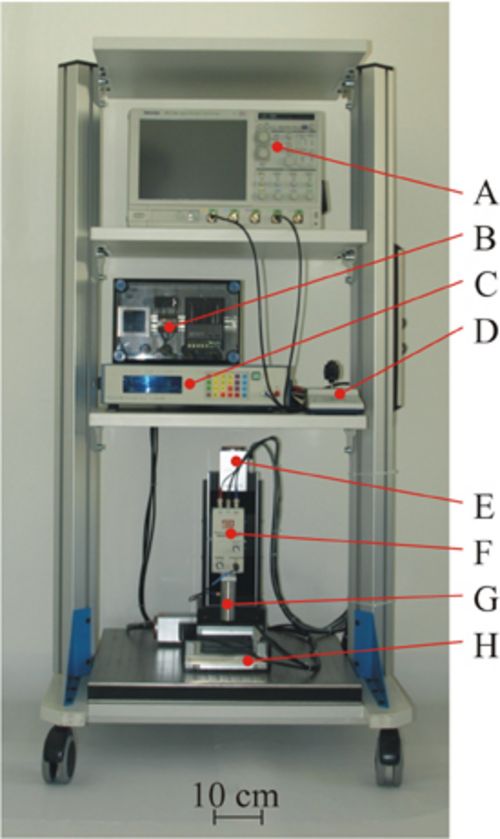 Figure 1: The image shows the realized measurement setup of the ultrasound microscope. All components are placed in a mobile Rack except the controlling computer. The setup consists of the transient recorder (A), the water temperature controlling unit (B), the pulser/receiver (C), the motor-controller (D), the mechanical positioning unit (E), the remote-pulser/receiver (F), the spherically focused ultrasound transducer (G) and the water tank (H).
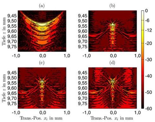 Figure 2: (a) shows a B-mode image (normalized; in dB) of a wire target (diameter 45 µm; orientated in y-direction), which is located in the negative defocus-region of the transducer. In (b) one can see the SAFT-image, which was calculated using a common algorithm for synthetic focusing. The panels (c) and (d) show the results of two modified SAFT-algorithms (SAFT-Variant 1 and SAFT-Variant 2). In these algorithms the characteristic of the transducer surface for both transmission and reception is considered in different manner. As opposed to (b) the signals with high amplitudes are rather concentrated in (c) as well as in (d). Hence both SAFT-Variant 1 and SAFT-Variant 2 provide a superior spatial resolution as the common SAFT-algorithm.
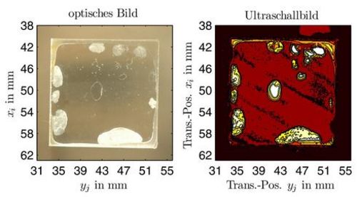 Figure 3: The left panel shows an optical image of two transparent Perspex plates which were glued. One can see that there are many inadequately glued regions where delaminations occur. The right panel shows the ultrasound image (C-mode image) of the glued region. Due to inhomogenities the incident pressure waves are reflected which results in a high output signal of the transducer (bright regions in the C-mode image).